JAI HIND HIGH VACUUM PUMP
GST : 07ALKPM3401E2ZG
Call us
08045477598
Call us
08045477598
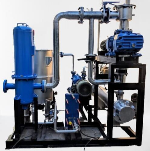
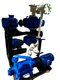
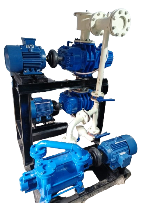
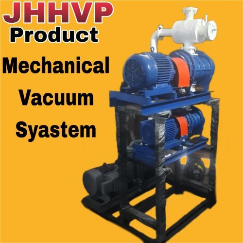
MECHANICAL VACUUM BOOSTER SYSTEM.
OPERATING MANUAL
Mechanical booster pumps have lobe type rotors driven by timing gears. The rotors counter-rotate with very close clearances between each other And the pump cylinder. The rotors trap a volume of air between each Rotor and the pump cylinder. This is then carried to the exhaust side ofThe pump and discharged.This entrapment occurs four times per revolution. The entrained air is forcedAround the case to the blower outlet. Timing gears accurately position the impellers in relation to each other to maintain the minute clearances vital to the high volumetric efficiency of the pump.
APPLICATION:
Evaporative Concentration, Vacuum Distillation, Polymerization, Crystallization, Vacuum Impregnation, Vacuum Drying, Sterlization, Vacuum Cooling, Object Metallising, Roll Metallisation, Semi-conductor Processing, Manufacture of Vacuum & Microwave Tubes, Manufacture of GLS Automotive & Miniature Lamps, Tube Light Production, Sintering, Brazing, Electron Beam Welding, Heat Treatment, Ionic Nitriding, Tool Coating, Vacuum Casting, Degassing & Refining, Plasma Welding, Evaporation, Sputtering, Space Research and Development.
KEY FEATURES
Booster vacuum levels of backing pumps, thereby reducing process temperature Booster volumetric displacement, thereby reducing Process Time.

 Send Inquiry